Modular Master-Slave Monocore Worm
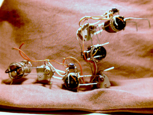
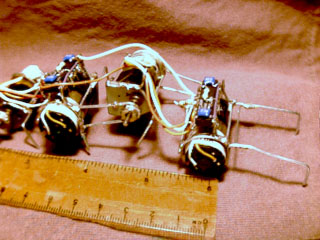
Alright, here it is!! Mod-Worm 1.0, a six motor device that crawls with
a catepillar-like rythmic motion, that is achieved by the master slave
monocore circuit that was created by Wilf Rigter. The control circuit is
spread across the entire length of the bot, localizing control of two motors
per control element. This gives Mod-Worm a very scalable/modular structure.
It can function with 2,4, or 6 motors and still achieve forward motion.(I
have video clips of all configurations here) I also imagine it would
scale even higher than six motors, with multiple ripples passing through
the length, to achieve a millipede type motion. The length of the structure
is very useful when climbing over obstacles; while one section of the bot
is dealing with the obstacle, the rest is pushing and pulling on the unobstructed
terrain to get over. One problem though, with this particular bot is that
it is fairly narrow, which can make it tip on to it's side when trying
to climb over uneven terrain. When on it's side it still moves, but in
more of a side-winder type locomotion, with very low gait efficiency. Two
other limitations of the bot are that it can't turn or reverse. I don't
see reversing as a very necessary function though. (I dont' think centipedes
and millipedes can reverse and they do just fine) Turning though, is something
that I'll have to investigate. Maybe for version 2.0 :)
click links to view the Mod-Worm crawling with different motor configurations:
6motor Mod-Worm
1.9meg quicktime
4motor Mod-Worm
1.4meg quicktime
2motor Mod-Worm
1.4meg quicktime
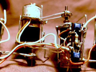
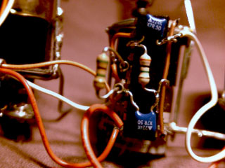
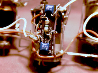
Electronics:
The controller is a Master-Slave Monocore. The length of the monocore pulse is determined by the 5.1 meg resistor. The 2 meg resistors are used to determine the amount of phase delay between the slaves and its master. There is one master Monocore and 5 slaves. The master is located at the tail of the bot. The motion starts here, and travels forward, resulting in a wave-like motion.
3- 74HC240s
6- .22 uF caps
5- 2 meg resistors
1- 5.1 meg resisrtor
6- Nihon Minimotors (BG Migro motors)
Battery- 3 cells from a 9 volt Duracell
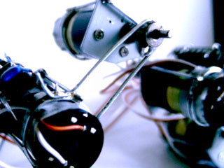
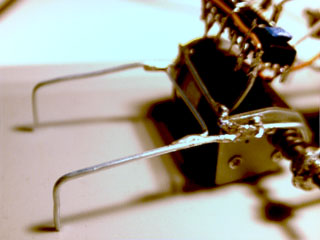
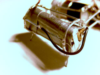
Construction:
The frame is constructed of jumbo paperclips. Mounting bracket were created for each motor, to allow a strong pivot arm to be attached. A brass hobby store wheel collar is used to mount the pivot arms to create the joints. The entire frame is used as ground, which allows the freeformed control circuits to be soldered directly to the frame. Wires between the control circuits are routed through an eye-loop that keeps them fairly organized. I left a lot of slack in the wires between the joints to allow freedom of movement. I had them a little tighter earlier on in development, but the bot tended to rip his own wires off, effectively killing itself. A tension spring is also used on the last section of the bot where the battery is housed. This keep the tail from lifting up too high, and also has a positive effect on the rest of the motion as the ripple moves forward.
any questions? email me:
Darrell Johnson
wundoba@pacbell.net
Brought to you by:
BICOREEOS
they're BEAMtastic!!!